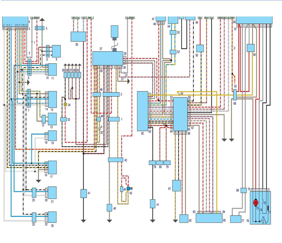
BMW E30 1984-1992 Electrical wiring diagrams

A complete guide to the electrical diagrams of BMW 3-series cars in the E30 body, produced from 1984 to 1992. The publication presents detailed wiring diagrams for all major systems: ignition, lighting, heating and air conditioning, window lifters, instrument panel, sound system and auxiliary equipment. The diagrams are accompanied by designations of contacts, wire colors and connector locations, which facilitates troubleshooting. This guide will become an indispensable assistant in electrical repairs, installation of additional equipment and restoration of the original BMW E30 wiring.
BMW 318i/325e/325ix/325i/325is/M3 Electrical Troubleshooting Manual
Central locking burglar alarm on-board computer
Scheme

L-Jetronic fuel injection system on the BMW E30

Description
1. Battery
2. Ignition Distributor
3. Ignition coil
4. Crankshaft angle sensor
5. Spark plugs
6. Generator
7. Starter
8. Oil pressure sensor
9. The gauge of temperature of a cooling liquid
10. Temperature sensor of the control unit
11. The electronic control unit
12. Connector
13. Throttle Position Sensor
14. Air flow meter
15. Fuel nozzles
16. Fuel pump relay
17. The ignition control unit
Heater and air conditioning

Description
1. Heater control knob lights
2. LED III
3. LED II
4. LED I
5. Heater fan switch (air conditioner evaporator)
6. 13-pin connector connecting heater wiring to center wiring harness
7. Connector connecting the front wiring section to the heater control panel
8. Heater fan fuse
9. Fuse (turning on 2nd fan speed)
10. Fuse for interior lighting, reversing signal, tachometer and mirror drive, mounted on a distribution block
11. Fan temperature sensor (91 ° С, 1 speed)
12. Fan temperature sensor (99 ° C, 2 speed)
13. A / C switch
14. Heater tap
15. Thermostat of the evaporator
16. Air conditioning control unit (on the heater control panel)
17. Auxiliary fan wiring connector
18. Relay of the 2nd speed of the additional fan (mounted on the distribution block)
19. The relay of the first speed of the additional fan (mounted on the distribution block)
20. Dehumidifier pressure sensor
21. Not used
22. Heater radiator fan
23. Evaporator fan
24. A contact socket of conducting of a high pressure sensor of a water separator and electromagnetic coupling of the compressor
25. Temperature sensor (mounted in the evaporator)
26. Temperature sensor (mounted in the heater)
27. The temperature sensor in the cabin (located on the left under the lower decorative panel of the cabin)
28. The electromagnetic clutch of the compressor
29. Additional fan
Motronic Engine Control Module for BMW E30

Description
1. Engine electronics
2. Crankshaft speed control unit
3. Temperature sensor connector
4. Air conditioning connector
5. Transmission wiring harness connector
6. Throttle Position Sensor
7. Air flow meter
8. Crankshaft speed sensor
9. Ignition torque sensor
10. Relay 1
11. Relay 2
12. Oil pressure sensor
13. The temperature sensor of the electronic engine control unit
14. Diagnostic connector
15. Distribution block
16. Battery
17. Spark plugs
18. Ignition Distributor
19. Ignition coil
20. Starter
21. Generator
22. Position sensor
23. Connector (automatic transmission disconnected on cars)
24. Coolant temperature sensor
25. Fuel injector
26. Solenoid
27. Distribution block
28. Socket for connecting the oil pressure sensor
29. Temperature sensor connector
30. A socket of connection of the fuel pump
31. Socket for connecting a control lamp for regular maintenance
32. Drive
33. Contact temperature sensor
Receiver and audio system

Description
1. The speaker on the right door
2. Front right speaker
3. Rear right speaker
4. Connector for connecting special equipment
5. Power window connector
6. Amplifier
7. Front left speaker
8. The speaker on the left door
9. Power connector
10. Antenna Connector
11. Receiver
12. Speaker tuner
13. The speaker is rear left
Start, charge system, direction indicators

1. Left reversing light
2. Right reversing light
3. Battery
4. Generator
5. Two-channel sound signal
6. Front right turn indicator
7. Direction indicator, rear right
8. Direction indicator, rear left
9. Front left turn indicator
10. Horn relay
12. Rear window defroster relay
13. Hazard warning relay
14. Starter
15. Ignition switch
16. Horn switch
17. Hazard warning light switch
18. Turn signal switch
19. Reversing light switch
